
ELM9410 | Power supply terminal for refreshing the E-bus, with diagnostics

ELM9410 | Power supply terminal for refreshing the E-bus, with diagnostics
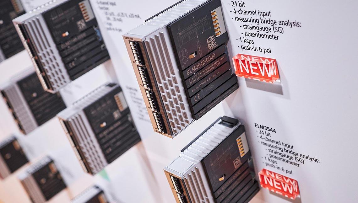
SPS 2019: Beckhoff Measurement Modules

The ELM9410 power supply terminal is used to increase the E-bus current. The exchange of data between EtherCAT Couplers and the connected EtherCAT Terminals takes place over the E-bus. Each EtherCAT Terminal requires a certain amount of current from the E-bus (see technical data at the respective terminal: “Current consumption E-bus“). This current is fed into the E-bus by the power supply unit of the respective EtherCAT Coupler. In configurations with a large number of EtherCAT Terminals, the ELM9410 can be used to increase the current supply to the E-bus by 2 A.
On account of three significant properties, the ELM9410 and the functionally identical EKM1101 EtherCAT Coupler are designed to meet the needs of high-precision analog measurement technology, e.g. with ELM3xxx terminals:
- To reduce interference in the connected terminal, both the E-bus supply US and the 24 V power contact supply UP are electrically isolated and filtered in the coupler. The power contact supply can carry a maximum load of 2 A.
- The extensive voltage and temperature monitoring provides assistance with commissioning and operation; results are displayed by LED and in the process image.
- The built-in three-axis position and vibration sensor allows a constant view of the mechanical situation in the control cabinet.
As a result, the ELM9410 can be used in special measuring situations instead of the conventional EL9410 supply. Mixed operation with EK1100/EL9410 is possible, however, not ensuring electrical isolation in this configuration.
Product status:
regular delivery
Product information
| Technical data | ELM9410 |
|---|---|
| Task within EtherCAT system | power supply terminal |
| Current consumption from US | 100 mA + (∑ E-bus current/4) |
| Current consumption from UP | 50 mA + load |
| Current supply E-bus | 2000 mA |
| Power contacts | max. 24 V DC/max. 2 A outgoing |
| Electrical isolation | 500 V (supply voltages Us/Up to E-bus/power contacts) |
| Diagnostics in the process image | yes |
| Special features | electrically isolated output voltages, reverse polarity protection, diagnostics of supply and output voltages, internal temperature and position and vibration |
| Weight | approx. 450 g |
| Operating temperature | -25…+55°C |
| Storage temperature | -40…+85°C |
| Relative humidity | 95%, no condensation |
| Vibration/shock resistance | conforms to EN 60068-2-6/EN 60068-2-27 |
| EMC immunity/emission | conforms to EN 61000-6-2/EN 61000-6-4 |
| Protect. rating/installation pos. | IP20/variable |
| Approvals/markings | CE |
| Housing data | ELM-30-xpin |
|---|---|
| Design form | metal housing with signal LEDs |
| Material | zinc die-cast |
| Installation | on 35 mm DIN rail, conforming to EN 60715 with lock |
| Side by side mounting by means of | double slot and key connection |
| Marking | – |
| Wiring | solid conductors (s): direct plug-in technique; fine-stranded conductors (st) and ferrule (f): spring actuation by screwdriver |
| Connection cross-section | s*: 0.2…1.5 mm², st*: 0.2…1.5 mm², f*: 0.25…0.75 mm² |
| Connection cross-section AWG | s*: AWG24…14, st*: AWG24…14, f*: AWG24…14 |
| Stripping length | 8…9 mm |
| Dimensions (W x H x D) | 30 mm x 100 mm x 95 mm |
*s: solid wire; st: stranded wire; f: with ferrule
Loading content ...
Loading content ...
Loading content ...
© Beckhoff Automation 2025 - Terms of Use